Introduction
Under the visionary leadership of Sheikh Mohamed Bin Rashid Al Maktoum vice president and prime minister of UAE and Ruler of Dubai, Palm Jumeirah township was inaugurated as an iconic project constructed off the coast of the emirate of Dubai. The project was built in the shape of a palm and has extended the stretch of Dubai coastline by more than 120 km. As Palm Jumeirah is the only modern structure seen from space, so is Metito’s on-site sewage treatment plant achieving many firsts.
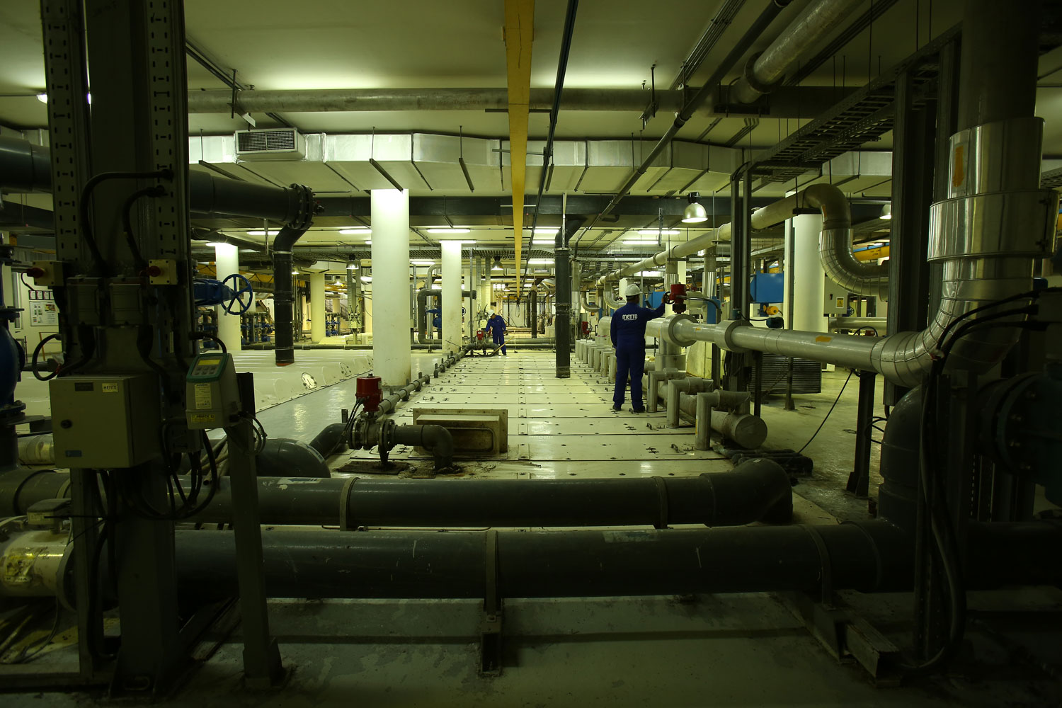
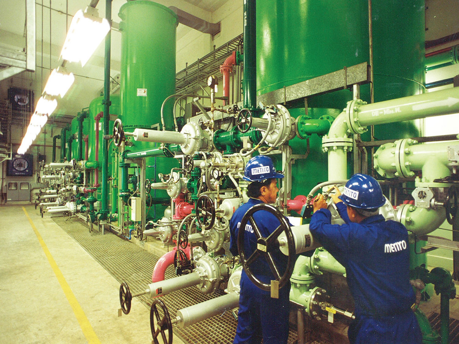
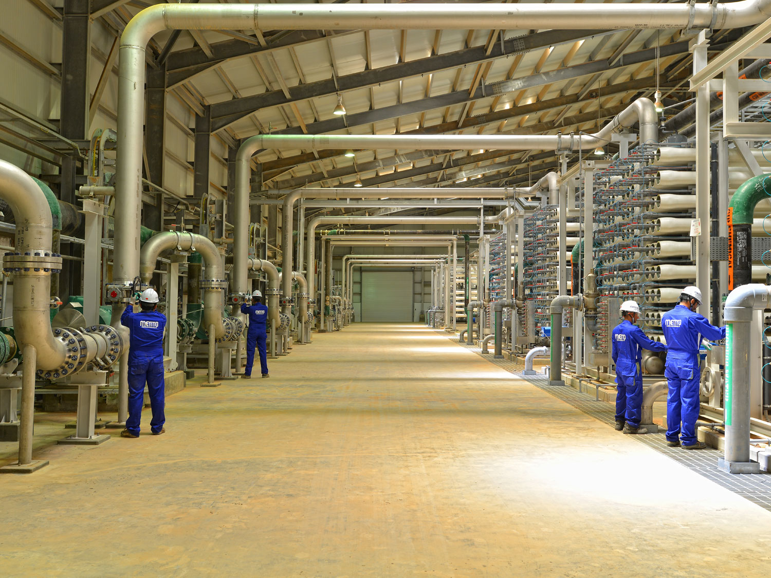
Being host to some of the world’s renowned dignitaries and celebrities meant that all associated utilities demanded challenging innovations, adherence, and commitment to maintaining the highest standards of environmental protection and architectural aesthetics. The location of the plant on prime land left extremely limited space for plant buildings and respective facilities. Architecturally, the treatment plant is inside a circular building constructed below ground to keep it invisible. The given geometry, limited space and underground conditions presented a very difficult task of arranging the equipment, facilities, and utilities. Metito employed the MBR (membrane bio-reactor) process technology which is the latest technology in treating waste. This process requires a considerably reduced footprint than other conventional schemes and has the added advantage of producing high-quality treated water.
Special designs were adopted for an approach to allow operational access and equipment maintenance. Limited headroom dictated the use of a specially designed serpentine monorail that covers the whole workspace. The status of the location demanded zero tolerance for any unpleasant odor emissions.
The ventilation system, dehumidifier and odor control units in the workspace were carefully designed taking into consideration these stringent demands.
Scope of Work
This included the detailed engineering, manufacture, inspection, supply, storage, installation, testing and commissioning, start-up, performance test and training of personnel at site. It also included operation and maintenance of the plant for eight years.
Plant General Information
The sewage treatment facility mainly comprises the following units:
- Inlet-works
- Biological treatment
- Sludge handling
- Chemical cleaning
- Electrical and control system
Plant Technical Characteristics
Raw sewage from the residential community is transferred to a main sewage lift station through two intermediate pumping stations.
The sewage treatment plant is designed to treat 18,000 m3/day of domestic sewage. The collected raw sewage is received through a 600 mm diameter underground main, and the incoming flow is metered before it enters the treatment units.
Plant Data Summary
| Average daily flow |
18.000 m3/day |
| Peak daily design flow |
21.700 m3/day |
| Peak factor |
2.5 |
| Peak hourly flow |
1875 m3/hr |
| Peak flow duration |
2 hours |
Influent Analysis
| Temperature |
22 -35 |
0C |
| BOD5 |
250 |
mg/l |
| COD |
500 |
mg/l |
| TKN |
55 |
mg/l |
| Assumed biodegradable TKN |
50 |
mg/l |
| Suspended solids |
250 |
mg/l |
| Phosphates |
8 |
mg/l |
| Alkalinity |
Min. 210 |
mg/l |
| Oil & Grease |
< 40 |
mg/l |
| pH |
6 – 9 |
|
| Ammonia nitrogen |
35 |
mg/l |
| Ambient Temperature |
10 minimum
50 maximum |
0C
0C |
Treated Water Quality
| BOD |
< 10 |
mg/l |
| COD |
< 50 |
mg/l |
| TKN |
< 5 |
mg/l |
| Suspended Solids |
< 10 |
mg/l |
| Ammonia – Nitrogen NH3(N) |
< 3 |
mg/l |
| Total Nitroge (TN) |
< 30 |
mg/l |
| Fecal Coliform |
< 10 |
mg/l |
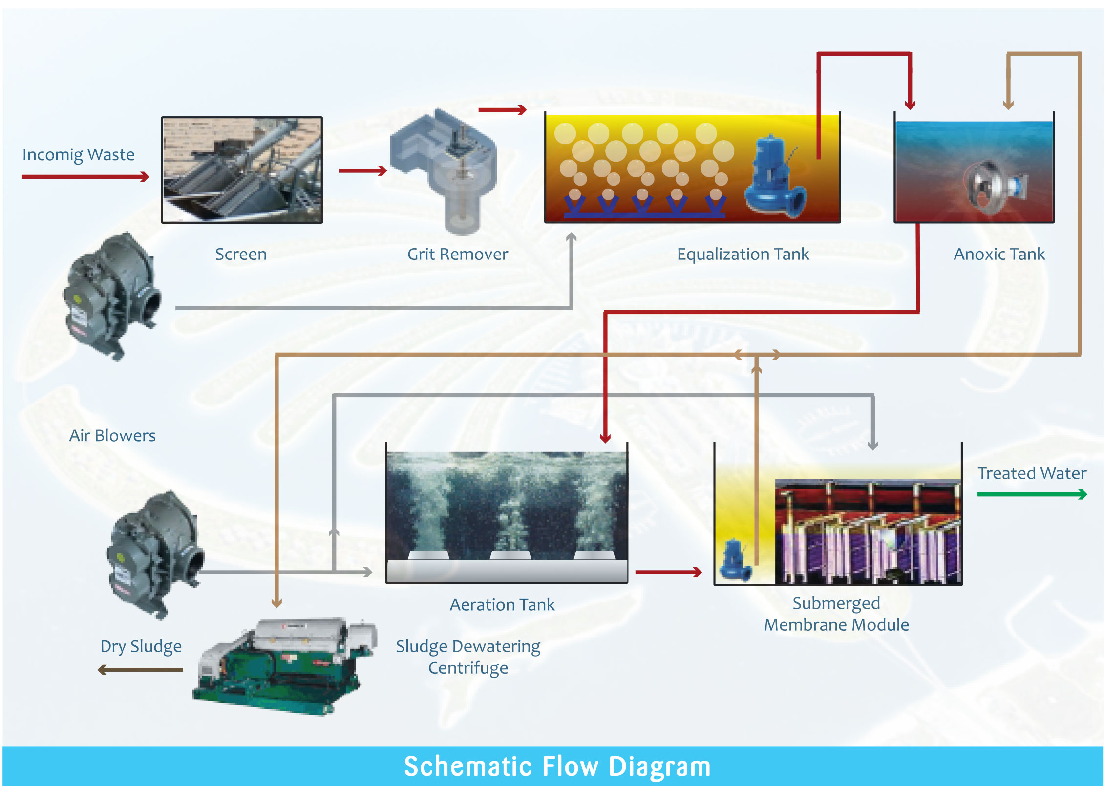
Process Description
Inlet Works
Metered raw sewage from the mains is released into a concrete channel through two 3mm perforated plate fine screens operating on a duty/standby basis. While screenings are removed, the screen surface is cleaned by spray nozzles as the basket is rotates. For clean and easy handling, the collected waste from the screens is compacted and dewatered up to 40% w/w. A Vortex type grit removal system with grit classifier is installed after the screens to remove heavy grit particles.
Partially treated raw sewage enters two compartment equalization tanks The tank is constantly purged with enough air to maintain the sewage in agitation and prevent it turning septic.
Downstream membrane treatment is divided into six process trains to cater for plant turndown and to provide flexibility in operation. The common pump sump has six duty/ six standby feed pumps dedicated to transfer sewage to the Anoxic tanks.
The biological treatment of each process train comprises the following process units:
Anoxic Tank
The anoxic tank receives partially pretreated equalized sewage that has been intimately mixed with recycled flow from the anoxic recycle pumps. The returned flows contain nitrate due to the nitrification of ammonia in the membrane tank. Bacteria utilize the soluble and particulate COD in the incoming sewage to effect de-nitrification under anoxic conditions. Submerged mixers in each anoxic tank keep the bacteria in suspension and homogenously mixed with the soluble nitrate.
Aeration Tank
Sewage from the anoxic tanks passes to the aeration tanks by gravity. The aeration tanks provide an aerobic environment to ensure nitrification of ammonia and oxidation of BOD achieved by the provision of high efficiency fine bubble diffused aeration. The air supply to the diffuser system is monitored and controlled automatically to maintain optimum residual dissolved oxygen (DO) concentration in the tanks.
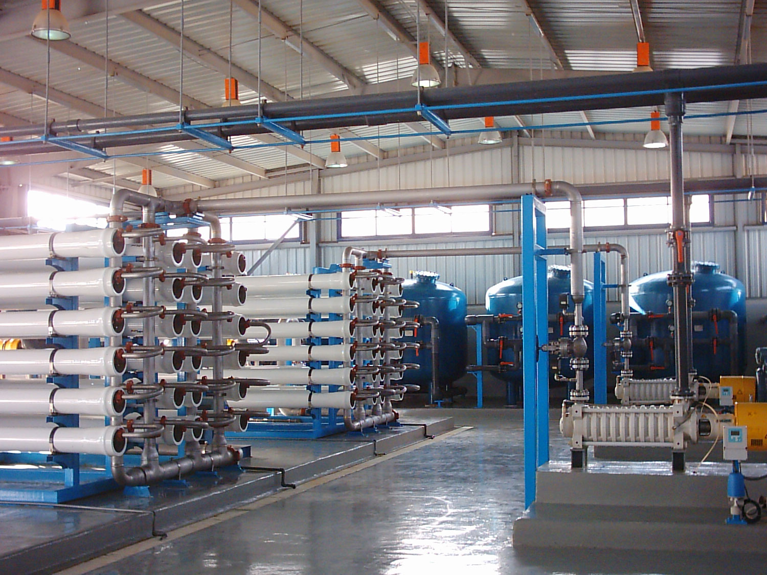
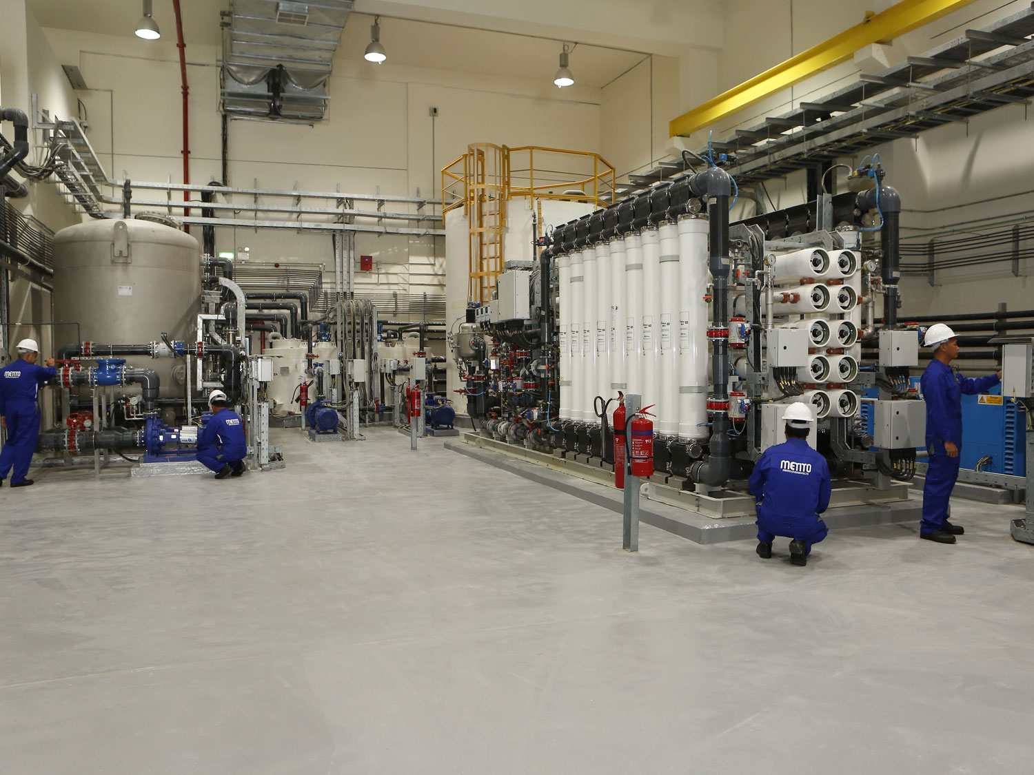
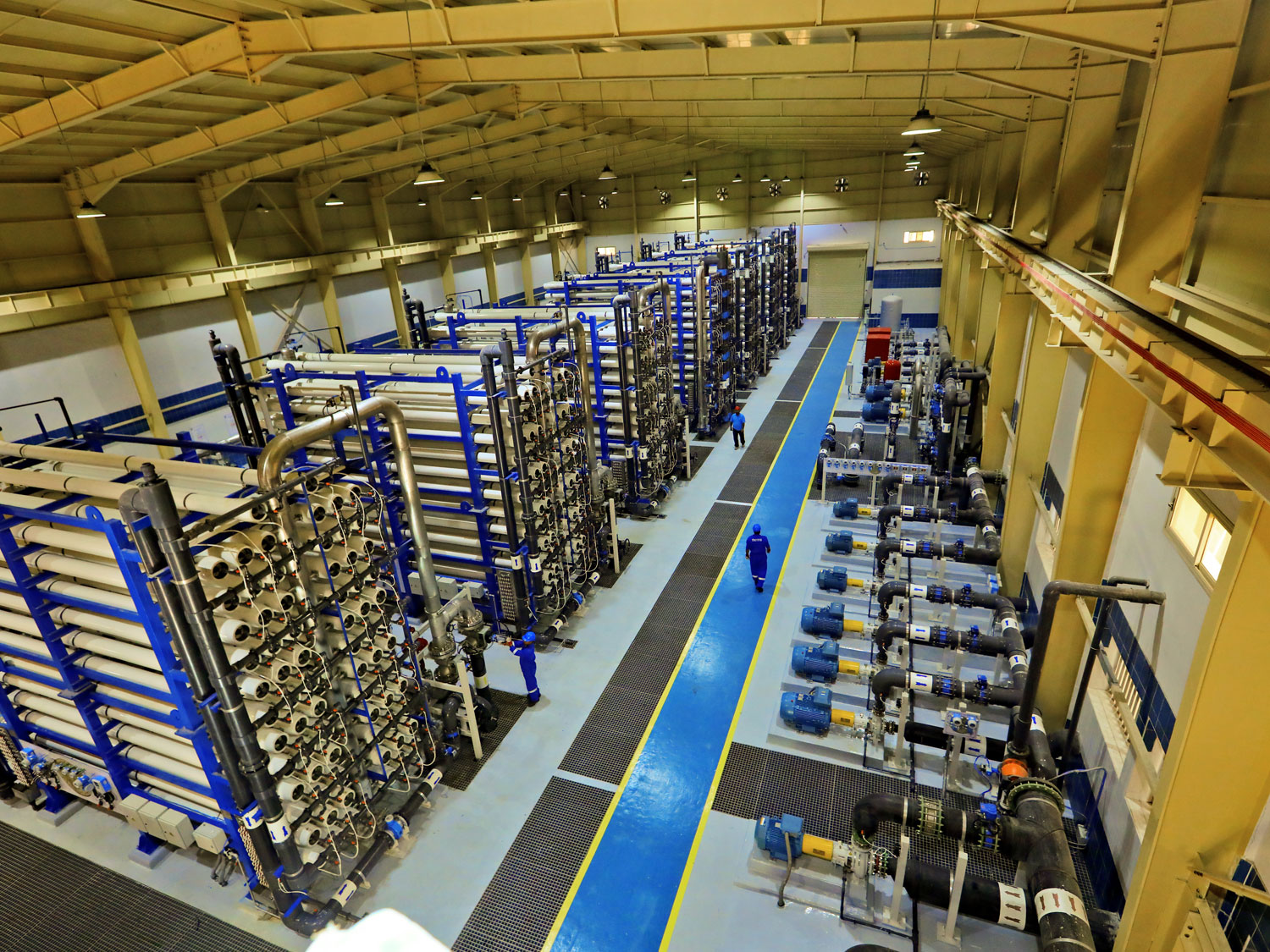
Membrane Bioreactor Tanks
Six membrane bioreactor tanks serve the function secondary aeration tank, whilst also assisting in the provision of air for the biological degradation processes. Each membrane tank contains 12 membrane units arranged in a double-deck configuration. To prevent surface, fouling, and membranes are continuously scoured by air supplied through diffused air pipe distributors below the membrane block.
Provision was made to chemically clean the membranes, if and when required. A diffuser flushing system is used to periodically flux the coarse bubble diffusers. Flux rate control is a critical operational feature hence flow through the membranes is controlled by modulating the permeate control valve to required flowrate through the flow meter on the permeate line.
Recycle Pump Control
The recycle pumps are subjected to intermittent operation to ensure a maximum recycle rate it low flow conditions. Intermittent operation is set according to the pre- determined schedule by a PLC.
Disinfection
The membrane process removes a large portion of bacteria from the sewage. Chlorination using sodium hypochlorite is imparted into treated streams to remove or inactivate any pathogenic bacteria that may grow in the tanks.
Sludge Digestion and Handling
Biological sludge is pumped to sludge digesters where it is digested and stabilized under aerobic conditions. Digested sludge is pumped to a dewatering centrifuge to produce sludge of 20 – 25% dryness. Concentrate from the centrifuge is returned to the plant inlet for recovery.
Electrical and Control Equipment
This includes state of an art SCADA system, PLC control panels, and MCCs. SCADA is implemented with a graphical depiction of the process as well as the graphical representation of process parameters and plant data that is also archived and retrievable. Power to the STP plant is fed from the facility substation which is equipped with dual incomers mains supply from DEWA as well as emergency supply from a generator. The design of the control equipment has taken into consideration the necessity for separate and independent operation of the MBR streams. so that failures in the control equipment associated with one stream will result in the shutdown of the affected stream only.
Project execution involved complying with the international standards and specifications drawn by the consultants. Important factors such as availability of plant, efficient use of manpower, high reliability and simplicity of maintenance have been considered in the design. The plant utilized minimum space whilst maintaining the overall architectural requirements. Technically, it provided a modern up to date process that ensures consistent water treatment quality. Metito completed this most challenging task to the entire satisfaction of the owner, and the successful operation of this entire complex was subsequently managed by Metito’s workforce.